Saturn boot cartridge (for Police Officer Smith)

RockinB

Established Member
Well, I never thought this could ever come true, but it has: I have created a prototype of a boot ROM cartridge for SEGA Saturn and it's been sooo much fun manufacturing the PCB!

pos_boot_cart_inserted_close.jpg


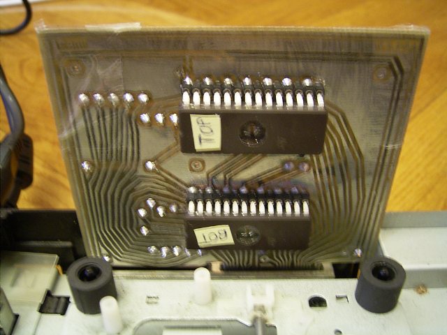
The circuit is very basic and simple, it just connects two 8bit EPROMs with 32kB each to the cartridge connector. It's targeted to just contain a boot up executable, to get our game Police Officer Smith running on an unmodified Saturn. I got me a whole stock of tools, accessories and all stuff needed to make this thing (EEPROM programmer, UV-erase lights, dremel, lot's of chemicals, PCB material and so on).

pos_boot_cart_inserted.jpg


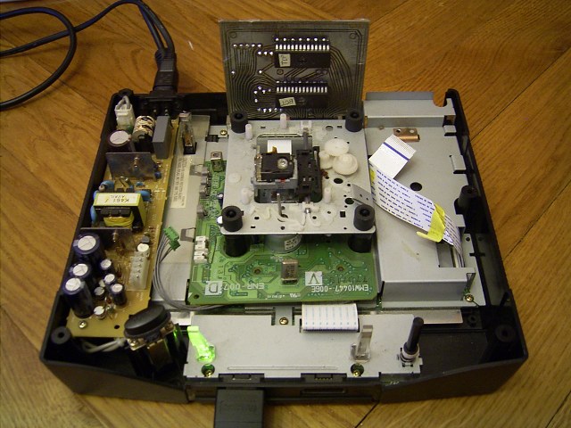
I've created a test application for debugging, it's the Memory Viewer from the Save Game Manager. I tried it out on yabause emulator first, then I programed it on an Action Replay cart and finally on my custom build cart. The app worked fine for debugging the cart. I could first boot up with the AR on an old damaged Saturn and then replace the AR with my cart. Here's a video from youtube: http://www.youtube.com/v/giCAxtRmeoY

You may have experienced by yourself that the Saturn cartridge port isn't that much reliable. Inserting an Action Replay doesn't always work right the first time, the insertion depth often must be corrected. So I'm surprised that the prototype cart works much better in that concern.

The two most interesting things about it are:

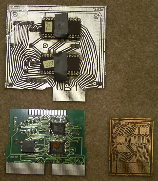
1) the PCB was made without any photo mask and UV light. Let me call it the "laser printer, flat iron and bucket method"

2) have a detailed look on the cartridge connector. The big part is missing, I only use the small part and it works! This makes it possible to create a cost effective version.

pos_boot_cart_size_compare.jpg
 
Well, that's quite interesting :)

How long did it take, on the whole ? (including PCB designing, etc. )
 
Nice job getting your etch setup working. Have you tried smaller spaces/traces yet?


I didn't realize that the critical stuff was only on that part of the connector; I suppose that's what I get for staring at an Action Replay 4M Plus so much. With a 16-bit surface-mount chip (probably need SO44 package to stay sane), the "half-cartridge" could be very small. With a couple additional chips, a lot could be done with that subset.
 
And somebody beat me to it, hahahahaaa :p


Extremely awesome work man :D


I'd love to see some schematic now :3


one reasons the Action Replay carts work poorly is because the cart edge contacts are tinned, and the oxide layer that forms on the tin is not very optimal. I scraped the tin coat off my cart and things work everytime now, no need to mess around with the cart in the slot :)
 
TmEE said:
I'd love to see some schematic now :3
Schematics for a ROM-only cart are not very exciting. Rockin'-B has a pinout on his site, and it's basically just a matter of matching up the signals to whatever memory configuration you're using.
 
Wow, thanks guys for your interest :)

Runik said:
How long did it take, on the whole ? (including PCB designing, etc. )
Longer than it would have taken someone more experienced than me. I'd say two weeks (including some days pause) for ordering everything needed, making 3 layout revisions (two can be seen on one of the pictures) and etching two pcbs on both sides. I also had to create a PC tool to convert the binary to two EPROM binaries, as the address and data pins are not connected one-on-one, instead I mixed pins such that the layout works best. However, the most time consuming part is to remove the paper from the copper, after I applied both together with a flat iron. The laser printer color is like glue between them. In the first place, I gathered information about the cart port, the BIOS and related technical stuff, then I looked around to choose the right ICs and the cheapest shops (This took one or two weeks, in addition). The prototype cart is also "completely" tinned.

ExCyber said:
Have you tried smaller spaces/traces yet?

Yes, at first I was trying to make it as small as possible. You can see the small PCB of size 37mm x 50mm on one of the images (note: the traces are a bit damaged while etching, I added a burn-in work step later to avoid this). It's no problem to make smaller traces with that method. But after realizing that my drill equipment can't reach the precision needed to drill in the holes, I figured size doesn't matter for the prototype and I made a redesign of the layout. The final POS version will be much smaller, with EPROMs in PLCC32 cases, instead of DIP28.

ExCyber said:
I didn't realize that the critical stuff was only on that part of the connector;
The pcb size (and the costs) shrinks significantly when using only the small connector. So I've been excited about the idea and just tried it out. I wasn't sure if it could work this way. The ROM size is limited to 64 kB, because of a lack of address bits. The larger connector contains the higher address bits. I'm pretty sure that beyond the address bits shown on the incomplete cart port schematic, there exist about 5 more address bits and you can guess their location.

ExCyber said:
Schematics for a ROM-only cart are not very exciting. Rockin'-B has a pinout on his site, and it's basically just a matter of matching up the signals to whatever memory configuration you're using.

He's right. The pure circuit is absolutely basic. I'm especially lucky that the OE and CE active level on the cart port matches that of the EPROMs. It's not documented anywere.

TmEE said:
one reasons the Action Replay carts work poorly is because the cart edge contacts are tinned, and the oxide layer that forms on the tin is not very optimal. I scraped the tin coat off my cart and things work everytime now, no need to mess around with the cart in the slot :)
Interesting, do you think cleaning it with acetone might help? Or may I just apply an additional (very thin) tin layer?
 
RockinB said:
Interesting, do you think cleaning it with acetone might help? Or may I just apply an additional (very thin) tin layer?


Acetone will temporairly help since the oxide layer will return very shortly... adding another layer will not help since the oxide layer will return shortly.

Only best option is to scrape or sand the layer off. I never tin the cart edges or controller board button contact points, all of homemade boards that I have made and have had this tin coating done don't work well at all. That's one reasons why my MD2 flashcart(for which I'll make a Saturn adaptor :p) uses a busted pirate MD cart instead of my homemade tinned edged board.

http://www.fileden.com/files/2008/4/21/1876835/MDflash0.jpg

http://www.fileden.com/files/2008/4/21/1876835/MDflash1.jpg

http://www.fileden.com/files/2008/4/21/1876835/MDflash2.jpg
 
TmEE said:
...my MD2 flashcart(for which I'll make a Saturn adaptor :p) uses a busted pirate MD cart instead of my homemade tinned edged board.

http://www.fileden.com/files/2008/4/21/1876835/MDflash0.jpg

http://www.fileden.com/files/2008/4/21/1876835/MDflash1.jpg

http://www.fileden.com/files/2008/4/21/1876835/MDflash2.jpg

Wow, that's crazy :rock:! I see at least three chips connected to the cut-out original pcb cart, what types are they? Oh, there's an led attached, too. I think it's difficult to not make wrong connections when so much wires are involved. The case is an original one, right? Manufacturing a good-looking case is one big problem for me, too. What else can you tell about your cartridge?
 
These 3 chips dangling on wires are an EEPROM mapper, for games saves for the MD game I'm making (and for which I make a sequel on Saturn, which is going to be a cart game, and thanks to you, it will go simpler :D).

There's 2x Flash chips there, there's 1 under the one on adaptor you can see. I really have to try out the laser printer + iron method, my stuff is done with weather proof marker and some artistic skills :p

2x 8bit wide 16MBit AMD flash chips are used, and a 93C66 EEPROM chip for saves, and some logic chips to get EEPROM managed. The LED is to indicate "power on" and "chip erase in progress".

The case is also stolen from a pirate cart, label is made with MS-Paint and printed with an ink printer, and I put some transparent glue film on it to get the "shine" :3
 
That cart must be quite more complicated than mine. Is the genesis version already fully functional?

TmEE said:
I really have to try out the laser printer + iron method, my stuff is done with weather proof marker and some artistic skills :p

To my surprise I found out there exists an english step-by-step explanation of the process. It's funny! http://thomaspfeifer.net/direct_toner_pcb.htm

I've heard of the water proof marker-method, I'm using such a marker to correct some holes or gaps in the layout on the copper, that can occur when the paper isn't easy to remove.
 
See the year number on the cart.... it has been in use since 2006 !!! It got the EEPROM mapper in 2007... the cart has had some few thousand writes and its a vital part in my MD dev and general MD based entertainment needs, lol

Since its 32Mbit, it runs nearly all games.


And that link is total jawusumness :D :D :D

Now to find myself a laser printer..... and see if my iron chloride mix is good to go. This makes the making of surface mount based boards much much simpler :D
 
Raster said:
Wow, great news. Is this generic enough for other games to use the boot cartridge?

At the moment, it's not that generic. To put a game on it, I take a standard Saturn executable of up to 60kB size and append it to a ripped and hex-edited IP.BIN. Then I use a self written tool to reorder the bits and split it up into two binariy streams, one for each of the eproms. With an eprom programmer, I put it on the one-time-programmable or uv-erasable eproms. Afterwards, the eprom chips are applied on the pcb.

It is no problem to link a Saturn binary into different memory regions, which allows to overcome the 60kb restriction. The rest would just be loaded from a CD (without IP.BIN). So currently a homebrew game needs slight modifications to work with the cart.

This cartridge was constructed for the sole purpose of booting Police Officer Smith, at the lowest possible cost (!), with the option to prevent it being spreaded as a torrent or played on an emulator. Speaking in general, making a commercial homebrew release quickly results in about 35-50 Euro total material cost per unit. So I am warned to take care of the costs.

How generic it works is now just a software issue. I'm currently thinking just a bit about that being generic thing, as I already have plans that need my time. Apart from making a very small version of this simplest cart to think of, I'm also keen of trying out some more complex circuitry in the future. When the small one is done, I could possibly help someone out with it, if there should be request.
 
Nice work RockinB!

This is a nice accessory for playing Homebrew games (without a modchip). And since it won't let you play any bootleg "official releases", you should be clear of any legal entanglements.

I admire your pcb-manufacturing skills. This is a good way to test your designs. But if you do some shopping around, you will see that you can get professionally made pcbs quite inexpensively (especially if they are only single-sided or double-sided).
 
gameofyou1 said:
I admire your pcb-manufacturing skills. This is a good way to test your designs. But if you do some shopping around, you will see that you can get professionally made pcbs quite inexpensively (especially if they are only single-sided or double-sided).

Hello gameofyou1, nice to see you again.

You're right. The price varies much from company to company, the last shop I've visited would take about 5 Euros for a small series of pcbs. I will do the layout of the small pcb version with a standard tool like Eagle, such that I got the option to sent the same layout to a professional manufacturer.

I'm really curious how much the sole material and manufacturing of "gimme one unit of Police Officer Smith, please" will cost in the end. It will consist of a whole lot of parts with pcb being only one of them. Most likely biggest costs will be caused by the cartridge case....
 
well done Rockin'-B !!!! So you didn't give up with POS. This boot cart is really promising.:congrats:
 
ok, this is extremely cool. what im really interested in is making a cart with a substantial amount of (flash) memory(1GB) onboard and a separate programmer. any details you can provide on would appreciated.


:banana: :banana: :banana: :banana: :banana: :banana: :banana: :banana: :banana: :banana: :banana: :banana: :banana: :banana: :banana: :banana: :banana: :banana: :banana: :banana: :banana: :banana: :banana: :banana: :banana: :banana: :banana: :banana: :banana: :banana: :banana: :banana: :banana: :banana: :banana: :banana: :banana: :banana: :banana: :banana: :banana: :banana: :banana: :banana: :banana: :banana:
 
Gravis said:
ok, this is extremely cool. what im really interested in is making a cart with a substantial amount of (flash) memory(1GB) onboard and a separate programmer. any details you can provide on would appreciated.

This could be done using an SD-card. In addition to the EPROM, I would place a µ-controller on the pcb, interfacing to an sd-card (there are multiple example schematics available on the internet). The µC would need to be mapped to the upper address region (almost 32 MByte left) using the long connecter, since there is no smaller EPROM available.

We were thinking about using an SD-card for storing all game data, too, but found that to be far more expensive in all terms.
 
Back
Top