Here are some notes on how I hacked the 21 pin modchip to a 20 pin Saturn. [the one available from Jandaman]
21 pin Saturn:
//mod chip legend//
*=used but not altered
+=pad selector for 4MHz clock
X=used and replaced data stream
Y=signal conditioned ;<strobe>-||-/\/\/\-GND
*1 -> IC 20 315-5746 pin 7 [8MHz clock] pad B
*2 -> Ground
X3 -> SH-1 Pin 107 DATA
X4 -> SH-1 Pin 108 Stop packet strobe[response byte?]
5 -> SH-1 Pin 101 OE
6 -> SH-1 Pin 100 Start packet strobe[command byte?]
*7 -> SH-1 Pin 111 WR strobe
8 -> Ground
+9 -> unused R48 [alternate 4MHz location diff rev.?] pad 0019
10 -> YGR-019B pin 123
11 -> SH-1 Pin 79
12 -> Ground
Y13 -> YGR-019B pin 126 and 129 OE fetch data
+14 -> YGR-019B pin 125 and 131 [4MHz clock] pad 0014
X15 -> YGR-019B pin 130 CD buffer DATA
16 -> Ground
17 -> IC 39 VHC08 pin 2
18 -> YGR-019B pin 122
19 -> YGR-019B pin 118 via 300 Ohm R175
20 -> YGR-019B pin 128
21 -> YGR-019B pin 121
pin 15 data is switched on 157 multiplexer between original and GAL
pin 3 data is routed through EM78 pins 12,9
pin 4 data is routed through EM78 pins 7,8
20 pin Saturn:
1 -> SH-1 Pin 79 logic HIGH
2 -> Ground
3 -> SH-1 Pin 107 Data
4 -> SH-1 Pin 108 Stop packet strobe[response byte?]
5 -> SH-1 Pin 101 OE
6 -> SH-1 Pin 111 WR strobe
7 -> SH-1 Pin 100 Start packet strobe[command byte?]
8 -> Ground
9 -> JP5 [8MHz clock]
10 -> Ground
11 -> YGR-019B pin 124 ??? logic low
12 -> YGR-019B pin 125 Read strobe
13 -> YGR-019B pin 126 OE
14 -> Ground
15 -> YGR-019B pin 128 Data Read OE [?] active only during data fetch
16 -> YGR-019B pin 129 OE fetch data
17 -> YGR-019B pin 131 [4MHz clock]
18 -> YGR-019B pin 130 CD buffer DATA
19 -> Ground
20 -> R47 (4.7KOhm), not sure where the other side of R47 goes ATM...
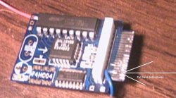
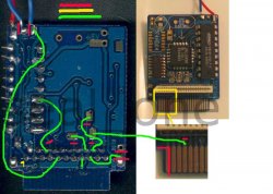
The pins that you have to cut and reroute on the modchip are
7,13,15,18
the hardest part is transferring 15->18
C=plastic ribbon connector
E=edge connector of modchip
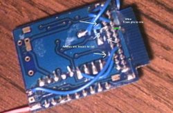
What traces to reroute:
Cut pin 7 C -> pin 6 on EM78
Connect Pin 6 EM78->pin 5 C
Cut pin 13 C -> Cap
Connect Cap-> pin 16 C
Cut pin 15 E -> pin 12 157
Cut pin 15 C -> pin 14 157
Cut pin 18 E -> pin 18 C
Connect pin 12 157 -> 18 E
Connect pin 14 157 -> 18 C
Connect pin 15 E -> pin 15 C
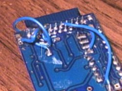
Remove solder from pads 0019,0014
Connect middle pad -> pin 17 C
remove solder/jumper/connection from A/B pads
Conect pad A [8MHz]-> Pin 9 C
Trim off pad 21 with dremel and you're done")
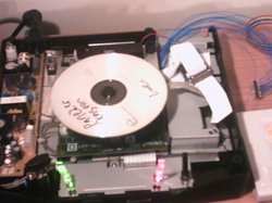
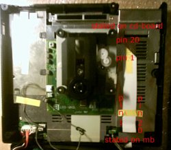
My problem now is that the ribbon cable is too short if you want to install the modchip in the Saturn motherboard. You should be able to install it into the CD drive connector, but I have wires for my logic analyzer soldered down to the pins which are in the way. My modchip has to have components facing away from the CD. Pin 1 is towards the rear of the console on my model 1 as pin 1 on my model 2 is towards the front. Is that not crazy or what?
Right now I just have the CD drive off its posts closer to the chip so the ribbon will reach. It's ugly as hell but it works. Just take care of the ordering of the pins. The connector on the CD drive on my model 1 Saturn are numbered backwards from the numbering scheme on the MB. But my model 2 is the same. The numbering used above is for the Connector on the MB.
I haven't had a chance to analyze what the Chip alters yet. Any pointers would be helpful. I'll have to do a lot more soldering and cutting to see before and after.
Looks like there's a command $4d to read the ring. If I put in a CD-R, it seems to check the country code first. Then, if that's ok, it moves to the outer ring and tries to read it. If it doesn't, it moves in closer and closer to the center in about 5 or so steps and then gives up. During this whole process, the first byte of the command packet, as I call it, reads $4d. Some of the CDC commands I think carry over directly to the drive like $01 is for get status.
Kudos to mal, ExCyber and the rest of the SegaXtreme gang for their wonderful posts.
I just want to say: MR Sporty, where are YOU?! I've tried to message and mail him, but I got no response. IIRC, he had the analyzer setup for before and after reads of the modchip. I wish I could talk more with you about what you've found and maybe do some more work to completely reverse this CD-ROM. Once it's all laid out, it should be a piece of cake to add a cypress Fx2 USB chip to emulate the CD-ROM or even add an IDE drive. I've already done it for the GameCube, but I'll admit it was much easier to reverse than this beast.
--Pinchy
21 pin Saturn:
//mod chip legend//
*=used but not altered
+=pad selector for 4MHz clock
X=used and replaced data stream
Y=signal conditioned ;<strobe>-||-/\/\/\-GND
*1 -> IC 20 315-5746 pin 7 [8MHz clock] pad B
*2 -> Ground
X3 -> SH-1 Pin 107 DATA
X4 -> SH-1 Pin 108 Stop packet strobe[response byte?]
5 -> SH-1 Pin 101 OE
6 -> SH-1 Pin 100 Start packet strobe[command byte?]
*7 -> SH-1 Pin 111 WR strobe
8 -> Ground
+9 -> unused R48 [alternate 4MHz location diff rev.?] pad 0019
10 -> YGR-019B pin 123
11 -> SH-1 Pin 79
12 -> Ground
Y13 -> YGR-019B pin 126 and 129 OE fetch data
+14 -> YGR-019B pin 125 and 131 [4MHz clock] pad 0014
X15 -> YGR-019B pin 130 CD buffer DATA
16 -> Ground
17 -> IC 39 VHC08 pin 2
18 -> YGR-019B pin 122
19 -> YGR-019B pin 118 via 300 Ohm R175
20 -> YGR-019B pin 128
21 -> YGR-019B pin 121
pin 15 data is switched on 157 multiplexer between original and GAL
pin 3 data is routed through EM78 pins 12,9
pin 4 data is routed through EM78 pins 7,8
20 pin Saturn:
1 -> SH-1 Pin 79 logic HIGH
2 -> Ground
3 -> SH-1 Pin 107 Data
4 -> SH-1 Pin 108 Stop packet strobe[response byte?]
5 -> SH-1 Pin 101 OE
6 -> SH-1 Pin 111 WR strobe
7 -> SH-1 Pin 100 Start packet strobe[command byte?]
8 -> Ground
9 -> JP5 [8MHz clock]
10 -> Ground
11 -> YGR-019B pin 124 ??? logic low
12 -> YGR-019B pin 125 Read strobe
13 -> YGR-019B pin 126 OE
14 -> Ground
15 -> YGR-019B pin 128 Data Read OE [?] active only during data fetch
16 -> YGR-019B pin 129 OE fetch data
17 -> YGR-019B pin 131 [4MHz clock]
18 -> YGR-019B pin 130 CD buffer DATA
19 -> Ground
20 -> R47 (4.7KOhm), not sure where the other side of R47 goes ATM...
The pins that you have to cut and reroute on the modchip are
7,13,15,18
the hardest part is transferring 15->18
C=plastic ribbon connector
E=edge connector of modchip
What traces to reroute:
Cut pin 7 C -> pin 6 on EM78
Connect Pin 6 EM78->pin 5 C
Cut pin 13 C -> Cap
Connect Cap-> pin 16 C
Cut pin 15 E -> pin 12 157
Cut pin 15 C -> pin 14 157
Cut pin 18 E -> pin 18 C
Connect pin 12 157 -> 18 E
Connect pin 14 157 -> 18 C
Connect pin 15 E -> pin 15 C
Remove solder from pads 0019,0014
Connect middle pad -> pin 17 C
remove solder/jumper/connection from A/B pads
Conect pad A [8MHz]-> Pin 9 C
Trim off pad 21 with dremel and you're done
My problem now is that the ribbon cable is too short if you want to install the modchip in the Saturn motherboard. You should be able to install it into the CD drive connector, but I have wires for my logic analyzer soldered down to the pins which are in the way. My modchip has to have components facing away from the CD. Pin 1 is towards the rear of the console on my model 1 as pin 1 on my model 2 is towards the front. Is that not crazy or what?
Right now I just have the CD drive off its posts closer to the chip so the ribbon will reach. It's ugly as hell but it works. Just take care of the ordering of the pins. The connector on the CD drive on my model 1 Saturn are numbered backwards from the numbering scheme on the MB. But my model 2 is the same. The numbering used above is for the Connector on the MB.
I haven't had a chance to analyze what the Chip alters yet. Any pointers would be helpful. I'll have to do a lot more soldering and cutting to see before and after.
Looks like there's a command $4d to read the ring. If I put in a CD-R, it seems to check the country code first. Then, if that's ok, it moves to the outer ring and tries to read it. If it doesn't, it moves in closer and closer to the center in about 5 or so steps and then gives up. During this whole process, the first byte of the command packet, as I call it, reads $4d. Some of the CDC commands I think carry over directly to the drive like $01 is for get status.
Kudos to mal, ExCyber and the rest of the SegaXtreme gang for their wonderful posts.
I just want to say: MR Sporty, where are YOU?! I've tried to message and mail him, but I got no response. IIRC, he had the analyzer setup for before and after reads of the modchip. I wish I could talk more with you about what you've found and maybe do some more work to completely reverse this CD-ROM. Once it's all laid out, it should be a piece of cake to add a cypress Fx2 USB chip to emulate the CD-ROM or even add an IDE drive. I've already done it for the GameCube, but I'll admit it was much easier to reverse than this beast.
--Pinchy