Hi, I'm new here and I've got a white japanese saturn and would like to mod it with one of jandamans mod boards. I've read pretty much anything regarding the mod of a saturn with a sanyo cd board without pc trap on this forum.
I've found two users that have done it.
Here is a quote from one of them:
The blue cable attached to a solder pad, that goes to the seventh pin?
Could anyone show me on the following pic, where exactely that would be? Or from where do I have to count the pins (I've already located the sanyo chip on the underside of the cd board, but I don't know where this solder pad is located.. yeah, I don't really know much about soldering^^')
In conclusion, my only real problem now is that I don't know the exaxt position, where to solder the blue cable on the underside of the sanyo cd board.
I would be really thankful if anyone could mark the exact position of the solder pad and seventh pin on the following pic.
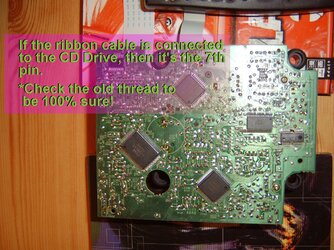
here's the pic of the sanyo cd board (sanyo chip located in the middle):
sanyocd.jpg
and another one, a little further away:
sanyocd2.jpg
I've found two users that have done it.
Here is a quote from one of them:
I have discovered a solution to make the mod work.
The Sanyo drive uses 16 Mhz instead of 8 Mhz.
On the drive's bottomside you can still see where
the 8 Mhz component was meant to be mounted.
I simply attached the blue cable to the solder pad
that goes to pin 7 on the Sanyo chip nearby. Power
cable went to 2nd power supply pin from the TOP.
Blue cable goes to A. As I have a HST-0019 Saturn,
I jumpered 0019 on the mod.
And now, everything works fine. biggrin.gif
I hope this information is helpful for all people
who have troubles with Sanyo drives.
The blue cable attached to a solder pad, that goes to the seventh pin?
Could anyone show me on the following pic, where exactely that would be? Or from where do I have to count the pins (I've already located the sanyo chip on the underside of the cd board, but I don't know where this solder pad is located.. yeah, I don't really know much about soldering^^')
In conclusion, my only real problem now is that I don't know the exaxt position, where to solder the blue cable on the underside of the sanyo cd board.
I would be really thankful if anyone could mark the exact position of the solder pad and seventh pin on the following pic.
here's the pic of the sanyo cd board (sanyo chip located in the middle):
sanyocd.jpg
and another one, a little further away:
sanyocd2.jpg