I found a mod chip for a 20 pin Saturn

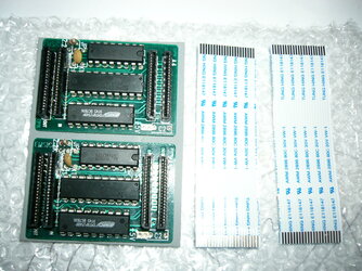
i found a mod chip at robwebb.clara.co.uk that arrived in the mail today. It has inputs for both a 20 pin Saturn as well as a 21 pin version. It also comes with an extra cable.

Here is a pic:

[attachmentid=1445]

I thought this information might help those who own the older models of the system. If anyone has already installed one of these before, please post here to let me or anyone else gain a better understanding of what the exact process is. I have a basic idea, but do not yet know for sure which cable is for the input, and for the output one(there was no instructions included). There is is also a wire that needs to be connected from the chip to a +5 volt power source somewhere inside the Saturn, and I will experiment based on some info I saw in another post:

http://forums.segaxtreme.net/index.php?showtopic=16264&st=15

and repost when I see some results.

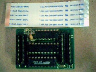
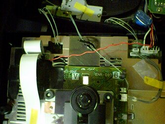
edit: here is the picture from the other forum which shows a lot more detail than mine.

edit2: whoops! thanks to dj898 for letting me know it was his photo I posted

[attachmentid=1444]

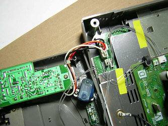
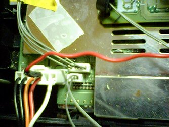
Notice on the top right corner of the chip the words "20 pin". It also says IN and OUT above each of the 2 sockets, though the words are blocked in this photo. The 2 sockets on the left side of the chip are labeled the same, but with "21 pin" text printed. So I assume this chip is suitable for both types of machine. On the bottom-right of the chip, where it says "+5V", I am guessing that a wire will be soldered at this point on the reverse side of the chip (where the actual solder joint is located) and then the other end of this wire is soldered to a suitable +5 Volt source which is probably the red wire that is connected to a white plug/harness located on the front right hand side of the machine's circuit board(it's the only one-you can't miss it). In the other topic post I linked above, the person C-S-B claims that it is possible to verify that the red wire is indeed the +5 volt power source by removing the small circuit board that is attached to the top half of the Saturn, and checking the labeling on the wire. If in the event that this isn't the case, or your system is different, the voltage of the wire should probably be tested with a multimeter first to make sure that it is indeed +5 volts there, because I have read posts from people who have had numerous problems installing mod chips and not knowing where they went wrong. Now I just have to figure out which cable goes to the "IN" slot, and which to the "OUT", and then if it works, I'll repost with some sort of a guide.
 

Attachments

  • p10504905lf.jpg
    p10504905lf.jpg
    782.3 KB · Views: 288
  • mod_chip.jpg
    mod_chip.jpg
    121.1 KB · Views: 318
by the way that photo is the one I u/l.

good to see someone is making good use out of it...

no I haven't had time to do anything with those...

will be interesting to mod one of my Cross Dev Saturn with this chip...

p.s. when you take photo with digital camera wait till it focus on the object and also, if you can, take the shot at the higest resolution and then down sample/crop using Photoshop or any other editing application...
 
Yup, I tested the wire first with a multimeter then found the labelling on the other side of the power supply board. :blush:

Its pretty easy to test though if the labelling isnt printed on your board, Just be careful not to touch the board with your hands while you have the power on. :sarcasm:

Afaik, the ribbon cable goes from the cd drive into the chip. You have to place the cable in to one side though as theres one pin not being used.

Good luck, tell me how you get on as i am planning to buy one. :D
 
Originally posted by C-S-B@Fri, 2005-09-02 @ 11:02 AM

Just be careful not to touch the board with your hands while you have the power on. :sarcasm:


now you tell me... :(

(rubbing my burnt finger tips... with 240 VAC Saturn)
 
Hey, thanks for the tips guys. I'll try it today with the red cable as the power source, I just have to figure out a good way to connect the two wires, I'm thinking of splicing into the red wire with the one from the mod chip, as I don't want to ruin the solder joint on the plastic plug with a new one.

p.s. when you take photo with digital camera wait till it focus on the object and also, if you can, take the shot at the higest resolution and then down sample/crop using Photoshop or any other editing application...

Thanks for the useful information. Unfortunately, I used a sony Clie, and it is very limited as to its settings. More light would have helped though...
 
Hi there. I am sorry for taking much longer to respond than I hoped. So far, I haven't had any success with the modboard. The cd player screen just comes up, with no boot screen before it, and the cd player doesn't spin at all, but with the words, 'checking disc format'. There is a description in one of the other forums by Mal:

http://forums.segaxtreme.net/index.php?showtopic=4368&st=15

about the various symtoms of a bad installation, and what they all indicate, and in this case I think it means I'm not getting power to the modboard. I emailed the guy in the UK that sold me the chip, and he provided me a link with install instructions:

http://www.nerdcave.de/stuff/modchip-howto.html

This is pretty much the way I installed it , but this person's is a PAL system, i think, because mine has the power source circuit board mounted on the top side of the Saturn, rather than the base as pictured. I will try mine again to see if I can get it going, and may ask for a replacement if I get no good results. What made me contact the guy for help in the first place is that after reading about the newer modboards having jumpers and such, I figured there's a good chance that since this board is made to work with both old and newer Saturns, that maybe I'd have to do something extra to it to make it work. Hopefully it's just a matter of bad soldering on the power wire, though I've never had a problem there before(tho I'm no expert).
 
Originally posted by tp221@Fri, 2005-09-09 @ 08:13 PM

This is pretty much the way I installed it , but this person's is a PAL system, i think, because mine has the power source circuit board mounted on the top side of the Saturn, rather than the base as pictured.


you must have very early revision if the PSU is attached to the top half of shell...

I had old Psy-Q dev saturn that was like that but it was JPN model and my prototype is like that as well...
 
That photo (above) is the same type as mine. I might have messed up before because I soldered the power wire directly to the joint on the top half of the machine where the 5 volts is (i had to unscrew that small circuit board to check markings first). It seemed a lot easier than trying to tap into the white power plug on the base part of the Saturn. I've never had problems with soldering before though, and I am tempted to believe that this is possibly flawed in manufacture because some of the solder joints on the modboard that hold the i.c. chips are only partly filled ie. there is a visible hole in about 8 or 9 spots. I think it is still quite possibly just the lack of power based on the similar errors that Mal describes in the other post i linked previous. But if it doesn't work after a second attempt, and I've already gone and readjusted ribbon cables and such, then I will ask the retailer for a replacement.
 
I have not had any success with this chip(20-pin). I reinstalled it after cleaning the contacts and I also tested the power wire for current and it is indeed getting power to the chip. I am beginning to think that his chip may be designed for PAL Saturns only. I say this, because my box is a MK-80000 NTSC with 1.00A bios, whereas the person who did the mod in the install link page used a PAL MK-80200-50 with 1.01a bios. There are those 3 jumper points on the top of the chip board that I want to troubleshoot, but I don't know what the risk is with them. I already ordered another same mod chip which I hope might work, in case this one is a dud.
 
hi,

i'm the guy who wrote the instruction on nerdcave.de.

any succes yet?

if there are issues with non-pal systems i'd like to add as much info as possible to my howto.
 
Originally posted by hideki@Tue, 2005-09-27 @ 09:05 PM

hi,

i'm the guy who wrote the instruction on nerdcave.de.

any succes yet?

if there are issues with non-pal systems i'd like to add as much info as possible to my howto.

[post=140013]Quoted post[/post]​


Hello,

I too have this modchip and am experiencing the EXACT same problems as tp221. I also own a early MK8000 with NTSC BIOS 1.01. :(
 
Hi there. I have a second chip that I ordered from the same person. Unfortunately I haven't been able to get the first one to work yet, and I am very busy with other things right now- so I can't get to experimenting with this one right now.

What I hope may be the solution is the three points on the top of the board, labelled "JP". The vendor in the UK, Rob Webb, told me in an email that he thinks those stand for jumper, so I wonder if two points are joined correctly with a small wire, it will make the chip work with the MK-80000 model. I may be able to try this before this Monday. I'll be sure to post again with the results.
 
Hi again. I think my problem was that the mod chip was fried, either by design or by an error when I was installing it. The second chip I ordered worked fine, much to my surprise. It didn't require any jumper bridges or anything, just a wire attached to the 5v marking, and it worked right away. I couldn't believe it.

To Ojref, I'm sorry to hear you are having the same difficulties I did. I guess there's a chance that either you haven't installed it correctly, or the thing is broken. I'd sell you the other one I have , but I'm pretty sure it doesn't work. I messed around around with that idea I suggested earlier about the 3 solder points labelled JP, and I tried all 3 possible link combinations and it didn't do a thing(no cd activity). One thing that made it a lot easier for me, though was I bought some connectors from an electronics supply store (Active Tech) that are basically those small metal pin jacks that you have for hooking up the small wires from your computer case to the motherboard, say. If you solder one of those on the end of the mod chip Power wire, it fits snugly inside the top of the white plug to provide contact (w/the Red Power wire), and can be removed easily. Another thing, is that it is a really good idea to shield the chip from the shiny metal surface(if that's what it sits on. Electrical tape stuck to the underlying surface(but not covering vents ) works, and also the top of the chip if you want, since it will have to be secured somehow anyway. I'll include a picture of those metal connectors in case it isn't clear what I'm talking about.

So, I guess that there isn't really a problem with North American vs. Europe systems in this case, but the problem was maybe the chips are not all up to par, or else the things are really delicate when worked on (my soldering iron is 30 watt, and I'm sure that the 15 watt ones are better for this).
 

Attachments

  • close_up_power.jpg
    close_up_power.jpg
    176.8 KB · Views: 226
  • top_view.jpg
    top_view.jpg
    176.8 KB · Views: 196
  • mini_fit.jpg
    mini_fit.jpg
    101.5 KB · Views: 198
I tried to install mine and I get no cd activity, according to mal's test reports my saturn experiences these sintomes:

If the ribbon cable isn't properly inserted (either bridge):

-no boot up animation

-two large red spheres at the CD player screen

-no CD rotation

-displays "checking disc format"

Except I get:

Orange sphere - Yellow Sphere

Red Sphere - Yellow Sphere ( If I change the cables around)

The problem is I check all possible combinations I had to cut one pin out of each end of the ribbon cable (the one that connects from the modboard to the mainboard) does it matter what side I cut? I have a few 21 pin ribbon cables so I can test arround it would have been so easy if the modboards were supplied with 20 pin cables. There's also a possibility that the modb is not getting the +5V I must get a multimeter and see if that's the problem.
 
Ok I got the idea of cutting the right pin of the end of the ribbon cable that connects to the mainboard (from the modbord) but leaving the 21 pin end and that connects to modb, one end is 20 pin the other end is 21 pin, it worked!! I also used solder paste to solder the energy cable to the modboard I recommend using that.
 
How does it come? I've the same chip, from rob and it is not working.

I'm sure that I've installed it the right way, and I've a pal system.

for the 20pin ribbon, the pin we don't use is the one near the 5v ? true?

:S
 
Back
Top