fafling
Gear Supporter
480p is certainly there for compatibility with 31 khz arcade machine monitors. Maybe they planned to hook an STV board to such a monitor. Or it could have been used for a special monitor such as the Hi Saturn Navi LCD screen.
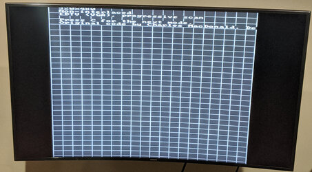
Anyway, to answer part of the original question and address issues with @stevekwok 's list, high res does not decrease VDP2 framerate, and neither does interlacing, except in single interlaced mode (and I'm not even sure that the console actually enforces that). Virtua Fighter 2, a high res double interlaced game, does run at 60 fps, not 15 !
The high res mode always has 60 fields per second which can display 60 different frames in progressive and double interlaced mode. VDP2 manual is incorrect about the latter in p. 14, and it seems SGL enforces a 30 fps framerate in double interlaced based on that inaccuracy (also reported by @Ponut and written in the SGL reference for slInitSystem). Since Jo Engine is using SGL, it inherits of that software limitation.