Hacked a 21pin mod to 20 pin saturn

Originally posted by mayden@Fri, 2005-01-21 @ 08:57 AM

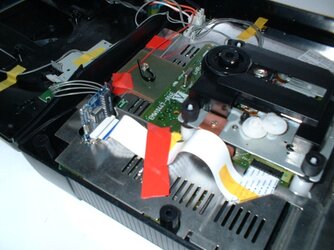
Good job seal1, the scheme looks pretty damn good! I can see the wire en cutting jobs clearly. The smal red ones are the cuts I presume? But could you be a bit more specific on the "2-4 desolder" thing? For example those two in the top-left corner. I can't really make out which thing to desolder. I presume the modchip in this photo is in it's original state, so it's pretty hard for a n00b like me to figure out how it should be in it's "modded" state.

edit: in the scheme, what's that small yellow dot in the bottom-left corner? A wire cut?

[post=128158]Quoted post[/post]​


the yellow in left bottom corner is only the number "one" for pin 1 - no cut only a mark.

(MID = middle pad between 0014 and 0019)

yes the small red ones are the cuts and/or the desolders.

desolders means - remove the solder iron to disconnect A-B or +5v-B or 0014-MID or MID-0019 if there is solder iron. I assume only 0014-MID is soldered per factory default which goes for 21pin-saturns before august 1996 (MID-0019 for 21pin-saturns during/from august 1996).

so per factory default you should desolder 0014-MID and desolder the wire from A coz it´s not needed for 20pin.
 
Is there anyone who will be willing to sell a working, modified modchip for use on a Model 1?

Also, does the fact that (as far as I can tell) both of my Saturns have 64-pin chips on the CD drive area mean that I can't fit a modchip?

I really hope not... :(
 
Originally posted by Drenholm@Fri, 2005-01-21 @ 04:35 PM

Is there anyone who will be willing to sell a working, modified modchip for use on a Model 1?

Also, does the fact that (as far as I can tell) both of my Saturns have 64-pin chips on the CD drive area mean that I can't fit a modchip?

I really hope not... :(

[post=128167]Quoted post[/post]​


I think we need to verify first in some 20pin models pinchy´s mod.

on which chip you counted the 64-pins ? which version is your cd-board ? how to identify ? ENR-007 and EMW10447-004E are the numbers stamped on my cd-board.
 
Thanks for your reply, seal1.

I will get back to you once I have checked out my 'Model 2'. I hope it's not just a Model 1 in a Model 2 case!! :D
 
Originally posted by Drenholm@Fri, 2005-01-21 @ 09:13 PM

Thanks for your reply, seal1.

I will get back to you once I have checked out my 'Model 2'. I hope it's not just a Model 1 in a Model 2 case!! :D

[post=128187]Quoted post[/post]​


seems better to go for a second "model 2" at ebay for some buck$, to be on the safe side than trying this mod ?
 
seems that i am the first one besides pinchy who actually tried this mod, or not?

it does function well, the metal shielding at the mb connector must be cut or pushed away for a few mm.

the ribbon cable is long enough to fit, but it forces the modboard against the metal shielding, which shorten some of the pins, so there must be something inserted to keep the distance.

the saturn looks like pinchy´s one, the cd-board is EMW10447-006E (a big V beneath) ENR-007 (a big inverse white D)
 
Originally posted by Drenholm@Sun, 2005-01-23 @ 10:01 AM

Yeah; I'm just hoping that I'll find a 21/32 Saturn!  :)

[post=128293]Quoted post[/post]​


all I know: 21pin must be with round button at least

but 32 or 64 - so how to identify ?
 
Originally posted by Sasurai@Mon, 2005-01-24 @ 02:17 PM

seems that i am the first one besides pinchy who actually tried this mod, or not?

it does function well, the metal shielding at the mb connector must be cut or pushed away for a few mm.

the ribbon cable is long enough to fit, but it forces the modboard against the metal shielding, which shorten some of the pins, so there must be something inserted to keep the distance.

the saturn looks like pinchy´s one, the cd-board is EMW10447-006E (a big V beneath) ENR-007 (a big inverse white D)

[post=128315]Quoted post[/post]​


ok sounds good.

did you:

>> Connect Pin 6 EM78->pin 5 C

or as identified "for me, my eyes/mind" on pinchy´s fotos (PHTO0005.JPG it looks like 6 C not 5 C)

>> Connect Pin 6 EM78->pin 6 C

(new wire from pin 6 em78 goes to upper row, which is even -> so 6 not 5 ?, coz you cutted connection to 7 which is lower row of connector, so upper must be 6 not 5 ?)

my 20pin saturn CD-board is EMW10447-004E (big V) and ENR-007 (big B)

no 32 or 64pin chip on topside of cd-board only a 24pin.

---

what is the magic about the 32pin, coz the extra wire from modchip to cd-board ? on my other saturn a 21pin modded with EMSIC7-modchip there is no extra wire. if this really needed or with other code on the modchip not necessary?
 
>> Connect Pin 6 EM78->pin 5 C

>or as identified "for me, my eyes/mind" on pinchy´s fotos (PHTO0005.JPG it looks like 6 C not 5 C)

it is pin 6, he probably mistyped it.

>my 20pin saturn CD-board is EMW10447-004E (big V) and ENR-007 (big B)

>no 32 or 64pin chip on topside of cd-board only a 24pin.

your cd-board is probably the same as mine, maybe an older/newer layout.

>what is the magic about the 32pin, coz the extra wire from modchip to cd-board ? on my other saturn a 21pin

>modded with EMSIC7-modchip there is no extra wire. if this really needed or with other code on the modchip not

>necessary?

the extra wire is for the 8mhz clock signal, which is needed to syncronize with the bus, which is stated in another thread is routed through pin 1 which directly goes to pad b, so you can also connect pad a+b instead of the cable to the cd-board (for the 21pin version, for the 20pin version the signal runs through pin 9 and that is why you connect pin 9 to pad a)
 
Originally posted by Drenholm+Sat, 2005-01-22 @ 12:35 AM--><div class='quotetop'>QUOTE(Drenholm @ Sat, 2005-01-22 @ 12:35 AM)</div><div class='quotemain'>Is there anyone who will be willing to sell a working, modified modchip for use on a Model 1?

[/b]


I second this actually. Assuming people can get this to work alright, I can see a lot of people wanting to buy some pre-modded chips for a fair bit ;)

Eh, could just buy a model 2 and normal mod... but the Saturn fan in me see's that as cheating =P For me, the idea of fully modding my original Model 1 Japanese Grey Saturn just seems great!

<!--QuoteBegin-madmalkav


If we made a big enough preorder to jandaman or any other store that stocks that stuff , you think they will get Xinga -or whatever that produces their chips- to made the changes in factory?

[/quote]

Do they actually still manufacture the mods? I assumed they stopped all that when the Saturn died, and the mods on the market now were just current stock...
 
Originally posted by Sasurai@Mon, 2005-01-24 @ 09:03 PM

>> Connect Pin 6 EM78->pin 5 C

>or as identified "for me, my eyes/mind" on pinchy´s fotos (PHTO0005.JPG it looks like 6 C not 5 C)

it is pin 6, he probably mistyped it.


thx, maybe I did the mod this weekend
 
It really does work! I just did the mod today. It was way easier then I thought and worked the first time I tried. I've got the EMW10447-004E board and I'm confirming it works great! The only thing I had to do to the case was bend a bit of metal to allow the chip to seat properly and I also used the soldering iron to melt a groove so the chip wouldn't scrape the top of the case when it was put back together.
 
I tried it on a model 1 saturn and it didn`t work. The audio player appears and I can see green cubes on both sides of the screen.

It`s the same with copies and original games. Always green cubes.

*Aaargh!* :blink:

What pin could be wrong?

I used the picture from seal1 and my saturn looks exactly the same like the one from seal1.
 
Originally posted by wolfchild@Wed, 2005-02-02 @ 06:45 AM

I tried it on a model 1 saturn and it didn`t work. The audio player appears and I can see green cubes on both sides of the screen.

It`s the same with copies and original games. Always green cubes.

*Aaargh!* :blink:

What pin could be wrong?

I used the picture from seal1 and my saturn looks exactly the same like the one from seal1.

[post=128899]Quoted post[/post]​


This sounds like the modchip isn't getting powered. Make sure you have the red wire soldered correctly the 5V source.
 
Thanks for your reply!

Originally posted by Givenbak@Wed, 2005-02-02 @ 08:31 AM

This sounds like the modchip isn't getting powered. Make sure you have the red wire soldered correctly the 5V source.

[post=128902]Quoted post[/post]​


Mmh, I'm pretty sure that it is soldered correctly to the 5V source. It`s the red wire from the power supply. And it`s connected to the left solder pad in the left upper corner of the backside of the chip.

Any other ideas?
 
Originally posted by wolfchild@Wed, 2005-02-02 @ 10:31 AM

Thanks for your reply!

Mmh, I'm pretty sure that it is soldered correctly to the 5V source. It`s the red wire from the power supply. And it`s connected to the left solder pad in the left upper corner of the backside of the chip.

Any other ideas?

[post=128905]Quoted post[/post]​


How do you have your modchip inserted into the board? I.e. do you have it plugged into the CD section where the ribbon cable starts or do you have it plugged into the other end so that its standing up? Which way is the frontside of the mod facing?
 
I have plugged it into the other end so that its standing up. The frontside of the mod is facing away from the cd-rom. I tried every position and tested all my soldering. Nothing than green cubes...

I think there are two possibilitys. Maybe I made some mistakes and fried the chip or I did something wrong with my "constructions". I think I will order me a new chip and try it a second time...

Thanks for your help!

But for this week I give up the fight... :blush:
 
Originally posted by wolfchild@Wed, 2005-02-02 @ 06:02 PM

I have plugged it into the other end so that its standing up. The frontside of the mod is facing away from the cd-rom. I tried every position and tested all my soldering. Nothing than green cubes...

I think there are two possibilitys. Maybe I made some mistakes and fried the chip or I did something wrong with my "constructions". I think I will order me a new chip and try it a second time...

Thanks for your help!

But for this week I give up the fight... :blush:

[post=128919]Quoted post[/post]​


The front side of the mod should be facing the cd-rom and the ribbon cable plugs straight into it. I'm going to try and post some pics tomorrow of my set up.
 
Here's the layout that works for me:

[attachmentid=1018]
 

Attachments

  • Chip_installed.jpg
    Chip_installed.jpg
    125.6 KB · Views: 854
  • Chip_installed.jpg
    Chip_installed.jpg
    125.6 KB · Views: 845
  • Chip_installed.jpg
    Chip_installed.jpg
    125.6 KB · Views: 844
Back
Top