Hello friends,
first of all, sorry for my bad english.
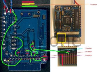
THIS PICTURE IS ORIGINAL BY SEAL1 !! I just added the Marks for the questions.
[attachmentid=1848]
1. Question
I know that there should not be any solder. But it is already shipped without any solder on that points.
Should I scratch the blue line away?
2. Question
What does the yellow sign means aspecialy at this point?
3. Question
Why should I cut between the green Wire and the 0014 ?
0019 and 0014 are already seperated by shipping.
4. Question
Is it right that you only need the red cable to plug in at the motherboards 5V conncetor?
Why are here 2 blue cables?
Thank you very much friends, a totaly pictured guide with every step would be awsome.
I am thinking about to do a complete Movie. So every noob can do it without any question. (plus GC and PS2 HDD).
greets,
skx
first of all, sorry for my bad english.
THIS PICTURE IS ORIGINAL BY SEAL1 !! I just added the Marks for the questions.
[attachmentid=1848]
1. Question
I know that there should not be any solder. But it is already shipped without any solder on that points.
Should I scratch the blue line away?
2. Question
What does the yellow sign means aspecialy at this point?
3. Question
Why should I cut between the green Wire and the 0014 ?
0019 and 0014 are already seperated by shipping.
4. Question
Is it right that you only need the red cable to plug in at the motherboards 5V conncetor?
Why are here 2 blue cables?
Thank you very much friends, a totaly pictured guide with every step would be awsome.
I am thinking about to do a complete Movie. So every noob can do it without any question. (plus GC and PS2 HDD).
greets,
skx